
Supported Membrane Formation, Characterization, Functionalization, and Patterning for Application in Biological Science and Technology
互联网
- Abstract
- Table of Contents
- Materials
- Figures
- Literature Cited
- Supplementary Material
Abstract
Supported membranes, formed as a single continuous lipid bilayer on a solid substrate, such as silica, have been used extensively as a model for protein?protein and cell?cell interaction, to study the molecular interactions at interfaces and the heterogeneities of plasma membranes. The advantages of a supported membrane system include the ability to control membrane composition and the compatibility it has with various surface?sensitive microscopic and spectroscopic techniques. Recent advances in micro? and nanotechnology have greatly extended the use of supported membranes to address key questions in cell biology. Although supported membranes can be easily made by vesicle fusion, the samples need careful preparation for this process to be efficient. The protocols in this unit comprehensively describe procedures to prepare, functionalize, and characterize supported membranes. Curr. Protoc. Chem. Biol. 2:235?269 © 2010 by John Wiley & Sons, Inc.
Keywords: supported membrane; supported lipid bilayer; small unilamellar vesicle (SUV); membrane functionalization; fluorescence recovery after photobleaching (FRAP); quantitative fluorescence measurement; photolithography
Table of Contents
- Introduction
- Strategic Planning
- Basic Protocol 1: Preparing Small Unilamellar Vesicles (SUVs) by Extrusion
- Alternate Protocol 1: Preparing SUVs by Probe Sonication
- Alternate Protocol 2: Preparing SUVs by Freeze‐Thawing
- Basic Protocol 2: Preparing Membrane Supports by Piranha Etching
- Alternate Protocol 3: Cleaning Substrates by Base Etching
- Alternate Protocol 4: Cleaning Substrates with Air/Oxygen Plasma
- Alternate Protocol 5: Cleaning Substrates with Ultraviolet Light/Ozone
- Support Protocol 1: Preparing Substrates with Diffusion Barriers (Gridded Substrates)
- Support Protocol 2: Preparing Substrates with Curvature Modulation
- Basic Protocol 3: Formation and Functionalization of Supported Membranes
- Support Protocol 3: Formation of Supported Membranes on Silica Beads
- Support Protocol 4: Formation of Supported Intermembrane Junctions
- Basic Protocol 4: Characterizing Supported Membranes
- Support Protocol 5: Measuring the Scaling Factor
- Reagents and Solutions
- Commentary
- Literature Cited
- Figures
- Tables
Materials
Basic Protocol 1: Preparing Small Unilamellar Vesicles (SUVs) by Extrusion
Materials
Alternate Protocol 1: Preparing SUVs by Probe Sonication
Materials
Alternate Protocol 2: Preparing SUVs by Freeze‐Thawing
Materials
Basic Protocol 2: Preparing Membrane Supports by Piranha Etching
Materials
Alternate Protocol 3: Cleaning Substrates by Base Etching
Materials
Alternate Protocol 4: Cleaning Substrates with Air/Oxygen Plasma
Materials
Alternate Protocol 5: Cleaning Substrates with Ultraviolet Light/Ozone
Materials
Support Protocol 1: Preparing Substrates with Diffusion Barriers (Gridded Substrates)
Materials
Support Protocol 2: Preparing Substrates with Curvature Modulation
Materials
Basic Protocol 3: Formation and Functionalization of Supported Membranes
Materials
Support Protocol 3: Formation of Supported Membranes on Silica Beads
Materials
Support Protocol 4: Formation of Supported Intermembrane Junctions
Materials
Basic Protocol 4: Characterizing Supported Membranes
Materials
Support Protocol 5: Measuring the Scaling Factor
Materials
|
Figures
-
Figure 1. Examples of functionalized supported membranes. (A ) Functionalization through polyhistidine and lipids with Ni2+ NTA headgroup. (B ) Functionalization through cysteine and lipids with maleimide headgroup. The art work in this figure is kindly provided by Dr. Lars Iversen. View Image -
Figure 2. Steps in the formation of SUV suspension. As lipids are dried, a thin film is formed in a round‐bottomed flask. Upon addition of water or buffer, the lipids self‐assemble into bilayers, which lift off the glass as spherical vesicles of various diameters. These multilamellar vesicles are then treated with sonication, extrusion, or freeze‐thawing to yield single‐layered vesicles of roughly uniform diameter. View Image -
Figure 3. Schematic depicting the steps in the preparation of glass substrates with micro‐fabricated thin metal lines (left) and curvatures (right). Bottom‐most two images are taken using a scanning electron microscope. Image on the left shows a substrate with parallel metal lines (700‐nm wide). Image on the right shows the cross‐section of a curved substrate. Scale bars are 6 µm. View Image -
Figure 4. Diagrammatic representation of the steps involved in supported membrane formation through vesicle fusion. (A ) Initial vesicle adsorption to surface of substrates. (B ) Fusion of adsorbed vesicles to form larger vesicles (if the initial vesicle is not large enough to rupture by itself) and flattening of adsorbed vesicles. (C ) Rupture of vesicles resulting in bilayer discs on the surface, and finally coalescence of bilayer discs to form a continuous two‐dimensional supported membrane. View Image -
Figure 5. The bottom portion of the figure shows an intermembrane junction (schematic, not to scale). Two lipid membranes, one of which is supported on a glass substrate, adhere. Adhesion drives mobile proteins (antibodies) into patterns of high‐ and low‐density zones. The upper portion of the figure shows a fluorescence image of proteins (20 µm by 5 µm); top view relative to the side view of the schematic). Adapted from Parthasarathy et al., . View Image -
Figure 6. Fluorescence recovery after photobleaching (FRAP). (A ) An image of a supported membrane prior to photobleaching. The field diaphragm is adjusted to the size of the bleached spot. (B ) Image of the supported membrane immediately after 10 sec of photobleaching. The field diaphragm can be seen fully opened for image acquisition. (C ) Image of the supported membrane after recovery. (D ) The recovery curve based on intensity measurements within the bleached spot. Fluorescent intensity at each time point is normalized to the initial intensity after background subtraction. Both initial and background intensities were obtained from (A). The half‐time of the recovery is 52 sec and the radius of the bleached spot is 27 µm; thus, the diffusion coefficient of the sample was estimated to be 3.1 µm2 /sec. View Image -
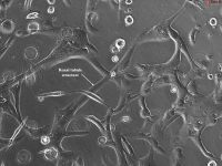
Figure 7. Effects of salt concentration on supported membrane formation. (A ) A fluorescent image of supported membrane containing 8% DOPG and formed under DI water showing large defects (black holes). (B ) Image showing vesicle budding (bright spots) in membrane formed with a salt solution (300 mM NaCl) of high ionic strength. (C ) Ca2+ induces defects on a supported membrane containing 25% POPA. Defects appear upon addition of 0.5 mM CaCl2 and gradually increase in size with time. (D ) and (E ) Examples of diffusion coefficients of supported membranes containing various DOPG concentrations as measured by FRAP. The membranes were prepared in deionized water. For the samples containing large defects, as shown in (A), FRAP was selectively measured in the regions that were defect‐free. (F ) Diffusion coefficients of supported membranes containing various DOPG concentrations as measured by FCS. The membranes were formed in the presence of 150 mM NaCl. All supported membranes contained a small amount of Texas Red‐DHPE for detection. Scale bars are 50 µm, unless specified otherwise. View Image -
Figure 8. Functionalized supported membranes on micro‐fabricated substrates. (A ) FRAP images of a functionalized supported membrane made of 5 mol% maleimide‐DHPE, 10 mol% DOPS, and 85 mol% DOPC on micro‐patterned, gridded substrate. Modified H‐Ras is linked to the supported membrane through its C‐terminal cysteine and then loaded with BODIPY‐GTP. The surface density of BODIPY‐GTP‐loaded Ras is ∼2000/µm2 . FRAP images clearly show that the diffusion of proteins in corrals made of chromium lines are restricted (center of the upper right quadrant), while proteins in areas lacking grids are free to diffuse. (B ) Fluorescent image of a supported membrane on a glass substrate with micro‐fabricated curvatures showing phase‐separation. The lipid composition, in mol %, of the bilayer is DOPC/DPPC/eggSM/cholesterol/DOTAP/TexasRed‐DPPE = 48.6/19.4/0/30/1.5/0.5. The fluorescent lipid TexasRed‐DPPE, which partitions strongly to the disordered phase (gray areas), is used to observe the effect of curvature on phase behavior of lipid mixtures. (C ) Bright‐field image of the underlying substrate shown in (B). Scale bars are 10 µm. View Image
Videos
Literature Cited
| Literature Cited | |
| Aegerter, M.A. and Mennig, M. 2004. Sol‐gel technologies for glass producers and users. Kluwer Academic Publishers, Boston. | |
| Akashi, K., Miyata, H., Itoh, H., and Kinosita, K. Jr. 1996. Preparation of giant liposomes in physiological conditions and their characterization under an optical microscope. Biophysical J. 71:3242‐3250. | |
| Amirfeiz, P., Bengtsson, S., Bergh, M., Zanghellini, E., and Borjesson, L. 2000. Formation of silicon structures by plasma‐activated wafer bonding. J. Electrochem. Soc. 147:2693‐2698. | |
| Anderson, T.H., Min, Y.J., Weirich, K.L., Zeng, H.B., Fygenson, D., and Israelachvili, J.N. 2009. Formation of supported bilayers on silica substrates. Langmuir 25:6997‐7005. | |
| Ashley, K.M., Meredith, J.C., Amis, E., Raghavan, D., and Karim, A. 2003. Combinatorial investigation of dewetting: Polystyrene thin films on gradient hydrophilic surfaces. Polymer 44:769‐772. | |
| Axelrod, D., Koppel, D.E., Schlessinger, J., Elson, E., and Webb, W.W. 1976. Mobility measurement by analysis of fluorescence photobleaching recovery kinetics. Biophysical J. 16:1055‐1069. | |
| Baumgartner, H., Fuenzalida, V., and Eisele, I. 1987. Ozone Cleaning of the Si‐SiO2 System. Appl. Physics A Mater. Sci. Proc. 43:223‐226. | |
| Bayerl, T.M. and Bloom, M. 1990. Physical properties of single phospholipid bilayers adsorbed to micro glass beads. A new vesicular model system studied by 2H‐nuclear magnetic resonance. Biophysical J. 58:357‐362. | |
| Blanchette, C.D., Lin, W.‐C., Ratto, T.V., and Longo, M.L. 2006. Galactosylceramide domain microstructure: Impact of cholesterol and nucleation/growth conditions. Biophysical J. 90:4466‐4478. | |
| Castellana, E.T. and Cremer, P.S. 2006. Solid supported lipid bilayers: From biophysical studies to sensor design. Surface Sci. Reports 61:429‐444. | |
| Chaiet, L. and Wolf, F.J. 1964. Properties of streptavidin biotin‐binding protein produced by Streptomycetes. Arch. Biochem. Biophys. 106:1‐5. | |
| Chiantia, S., Ries, J., and Schwille, P. 2009. Fluorescence correlation spectroscopy in membrane structure elucidation. Biochim. Biophys. Acta 1788:225‐233. | |
| Contino, P.B., Hasselbacher, C.A., Ross, J.B.A., and Nemerson, Y. 1994. Use of an oriented transmembrane protein to probe the assembly of a supported phospholipid‐bilayer. Biophysical J. 67:1113‐1116. | |
| Cremer, P.S. and Boxer, S.G. 1999. Formation and spreading of lipid bilayers on planar glass supports. J. Phys. Chem. B 103:2554‐2559. | |
| Dean, C., Scholl, F.G., Choih, J., DeMaria, S., Berger, J., Isacoff, E., and Scheiffele, P. 2003. Neurexin mediates the assembly of presynaptic terminals. Nat. Neurosci. 6:708‐716. | |
| DeMond, A.L., Mossman, K.D., Starr, T., Dustin, M.L., and Groves, J.T. 2008. T cell receptor microcluster transport through molecular mazes reveals mechanism of translocation. Biophysical J. 94:3286‐3292. | |
| DeRosa, R.L., Schader, P.A., and Shelby, J.E. 2003. Hydrophilic nature of silicate glass surfaces as a function of exposure condition. J. Non‐Cryst. Solids 331:32‐40. | |
| Doering, R. and Nishi, Y. 2008. Handbook of semiconductor manufacturing technology, 2nd ed. CRC Press, Boca Raton, Fla. | |
| Forstner, M.B., Yee, C.K., Parikh, A.N., and Groves, J.T. 2006. Lipid lateral mobility and membrane phase structure modulation by protein binding. J. Am. Chem. Soc. 128:15221‐15227. | |
| Galush, W.J., Nye, J.A., and Groves, J.T. 2008. Quantitative fluorescence microscopy using supported lipid bilayer standards. Biophysical J. 95:2512‐2519. | |
| Galush, W.J., Shelby, S.A., Mulvihill, M.J., Tao, A., Yang, P., and Groves, J.T. 2009. A nanocube plasmonic sensor for molecular binding on membrane surfaces. Nano. Lett. 9:2077‐2082. | |
| Giocondi, M.C., Seantier, B., Dosset, P., Milhiet, P.E., and Le Grimellec, C. 2008. Characterizing the interactions between GPI‐anchored alkaline phosphatases and membrane domains by AFM. Pflug. Arch. Eur. J. Physiol. 456:179‐188. | |
| Goksu, E.I., Vanegas, J.M., Blanchette, C.D., Lin, W.C., and Longo, M.L. 2009. AFM for structure and dynamics of biomembranes. Biochim. Biophys. Acta 1788:254‐266. | |
| Goldman, M.A., Graves, D.B., Antonelli, G.A., Behera, S.P., and Kelber, J.A. 2009. Oxygen radical and plasma damage of low‐k organosilicate glass materials: Diffusion‐controlled mechanism for carbon depletion. J. Appl. Phys. 106:013311. | |
| Gomez, E.W., Clack, N.G., Wu, H.J., and Groves, J.T. 2009. Like‐charge interactions between colloidal particles are asymmetric with respect to sign. Soft Matter 5:1931‐1936. | |
| Grakoui, A., Bromley, S.K., Sumen, C., Davis, M.M., Shaw, A.S., Allen, P.M., and Dustin, M.L. 1999. The immunological synapse: a molecular machine controlling T cell activation. Science 285:221‐227. | |
| Grogan, M.J., Kaizuka, Y., Conrad, R.M., Groves, J.T., and Bertozzi, C.R. 2005. Synthesis of lipidated green fluorescent protein and its incorporation in supported lipid bilayers. J. Am. Chem. Soc. 127:14383‐14387. | |
| Groves, J.T. 2005. Molecular organization and signal transduction at intermembrane junctions. Angew. Chem. Int. Ed. Engl. 44:3524‐3538. | |
| Groves, J.T. 2006. Spatial mutation of the T cell immunological synapse. Curr. Opin. Chem. Biol. 10:544‐550. | |
| Groves, J.T. 2007. Bending mechanics and molecular organization in biological membranes. Annu. Rev. Phys. Chem. 58:697‐717. | |
| Groves, J.T., Ulman, N., and Boxer, S.G. 1997. Micropatterning fluid lipid bilayers on solid supports. Science 275:651‐653. | |
| Groves, J.T., Parthasarathy, R., and Forstner, M.B. 2008. Fluorescence imaging of membrane dynamics. Annu. Rev. Biomed. Eng. 10:311‐338. | |
| Gureasko, J., Galush, W.J., Boykevisch, S., Sondermann, H., Bar‐Sagi, D., Groves, J.T., and Kuriyan, J. 2008. Membrane‐dependent signal integration by the Ras activator Son of sevenless. Nat. Struct. Mol. Biol. 15:452‐461. | |
| Hartman, N.C., Nye, J.A., and Groves, J.T. 2009. Cluster size regulates protein sorting in the immunological synapse. Proc. Natl. Acad. Sci. U.S.A. 106:12729‐12734. | |
| Hendrickson, W.A., Pahler, A., Smith, J.L., Satow, Y., Merritt, E.A., and Phizackerley, R.P. 1989. Crystal‐structure of core streptavidin determined from multiwavelength anomalous diffraction of synchrotron radiation. Proc. Natl. Acad. Sci. U.S.A. 86:2190‐2194. | |
| Hope, M.J., Bally, M.B., Webb, G., and Cullis, P.R. 1985. Production of large unilamellar vesicles by a rapid extrusion procedure—Characterization of size distribution, trapped volume and ability to maintain a membrane‐potential. Biochim. Biophys. Acta 812:55‐65. | |
| Huang, C.H. 1969. Studies on phosphatidylcholine vesicles . Formation and physical characteristics. Biochemistry 8:344‐352. | |
| Israelachvili, J.N. 1992. Intermolecular and surface forces, Second Edition. Academic Press, New York. | |
| Jaeger, R.C. 2002. Introduction to microelectronic fabrication, 2nd edition. Modular Series on Solid State Devices. Prentice Hall, Upper Saddle River, N.J. | |
| Jass, J., Tjarnhage, T., and Puu, G. 2000. From liposomes to supported, planar bilayer structures on hydrophilic and hydrophobic surfaces: An atomic force microscopy study. Biophysical J. 79:3153‐3163. | |
| Johnson, J.M., Ha, T., Chu, S., and Boxer, S.G. 2002. Early steps of supported bilayer formation probed by single vesicle fluorescence assays. Biophysical J. 83:3371‐3379. | |
| Kaizuka, Y. and Groves, J.T. 2004. Structure and dynamics of supported intermembrane junctions. Biophysical J. 86:905‐912. | |
| Kaizuka, Y. and Groves, J.T. 2006. Hydrodynamic damping of membrane thermal fluctuations near surfaces imaged by fluorescence interference microscopy. Phys. Rev. Lett. 96:118101. | |
| Kasi, S.R. and Liehr, M. 1990. Vapor‐phase hydrocarbon removal for Si processing. Appl. Phys. Lett. 57:2095‐2097. | |
| Keller, C.A., Glasmastar, K., Zhdanov, V.P., and Kasemo, B. 2000. Formation of supported membranes from vesicles. Phys. Rev. Lett. 84:5443‐5446. | |
| Kondoh, E., Baklanov, M.R., Bender, H., and Maex, K. 1998. Structural change in porous silica thin film after plasma treatment. Electrochem. Solid State Lett. 1:224‐226. | |
| Kunding, A.H., Mortensen, M.W., Christensen, S.M., and Stamou, D. 2008. A fluorescence‐based technique to construct size distributions from single‐object measurements: Application to the extrusion of lipid vesicles. Biophysical J. 95:1176‐1188. | |
| Legrini, O., Oliveros, E., and Braun, A.M. 1993. Photochemical processes for water‐treatment. Chem. Rev. 93:671‐698. | |
| Macdonald, R.C., Jones, F.D., and Qiu, R.Z. 1994. Fragmentation into small vesicles of dioleoylphosphatidylcholine bilayers during freezing and thawing. Biochim. Biophys. Acta Biomembr. 1191:362‐370. | |
| Maier, O., Oberle, V., and Hoekstra, D. 2002. Fluorescent lipid probes: Some properties and applications (a review). Chem. Phys. Lipids 116:3‐18. | |
| Manley, S. and Gordon, V.D. 2008. Making giant unilamellar vesicles via hydration of a lipid film. Curr. Protoc. Cell Biol. 40:24.3.1‐24.3.13. | |
| Manz, B.N. and Groves, J.T. 2010. Spatial organization and signal transduction at intercellular junctions. Nat. Rev. Mol. Cell Biol. 11:342‐352. | |
| Mayer, L.D., Hope, M.J., Cullis, P.R., and Janoff, A.S. 1985. Solute distributions and trapping efficiencies observed in freeze‐thawed multilamellar vesicles. Biochim. Biophys. Acta 817:193‐196. | |
| McIntire, T.M., Smalley, S.R., Newberg, J.T., Lea, A.S., Hemminger, J.C., and Finlayson‐Pitts, B.J. 2006. Substrate changes associated with the chemistry of self‐assembled monolayers on silicon. Langmuir 22:5617‐5624. | |
| Michel, B., Giza, M., Krumrey, M., Eichler, M., Grundmeier, G., and Klages, C.P. 2009. Effects of dielectric barrier discharges on silicon surfaces: Surface roughness, cleaning, and oxidation. J. Appl. Phys. 105:073302. | |
| Moon, D.W., Kurokawa, A., Ichimura, S., Lee, H.W., and Jeon, I.C. 1999. Ultraviolet‐ozone jet cleaning process of organic surface contamination layers. J. Vacuum Sci. Technol. A 17:150‐154. | |
| Mossman, K.D., Campi, G., Groves, J.T., and Dustin, M.L. 2005. Altered TCR signaling from geometrically repatterned immunological synapses. Science 310:1191‐1193. | |
| Nye, J.A. and Groves, J.T. 2008. Kinetic control of histidine‐tagged protein surface density on supported lipid bilayers. Langmuir 24:4145‐4149. | |
| Parthasarathy, R. and Groves, J.T. 2004. Protein patterns at lipid bilayer junctions. Proc. Natl. Acad. Sci. U.S.A. 101:12798‐12803. | |
| Parthasarathy, R., Cripe, P.A., and Groves, J.T. 2005. Electrostatically driven spatial patterns in lipid membrane composition. Phys. Rev. Lett. 95:048101. | |
| Parthasarathy, R., Yu, C.H., and Groves, J.T. 2006. Curvature‐modulated phase separation in lipid bilayer membranes. Langmuir 22:5095‐5099. | |
| Patty, P.J. and Frisken, B.J. 2003. The pressure‐dependence of the size of extruded vesicles. Biophysical J. 85:996‐1004. | |
| Paulick, M.G., Wise, A.R., Forstner, M.B., Groves, J.T., and Bertozzi, C.R. 2007. Synthetic analogues of glycosylphosphatidylinositol‐anchored proteins and their behavior in supported lipid bilayers. J. Am. Chem. Soc. 129:11543‐11550. | |
| Pfeiffer, I. and Hook, F. 2004. Bivalent cholesterol‐based coupling of oligonucletides to lipid membrane assemblies. J. Am. Chem. Soc. 126:10224‐10225. | |
| Pietsch, G.J., Kohler, U., and Henzler, M. 1994. Chemistry of silicon surfaces after wet chemical preparation—A thermodesorption spectroscopy study. J. Vacuum Sci. Technol. B 12:78‐87. | |
| Reinhardt, K.A. and Kern, W. 2008. Handbook of Silicon Wafer Cleaning Technology, 2nd edition. Materials Science & Process Technology Series. William Andrew, Norwich, New York. | |
| Reviakine, I. and Brisson, A. 2000. Formation of supported phospholipid bilayers from unilamellar vesicles investigated by atomic force microscopy. Langmuir 16:1806‐1815. | |
| Richter, R., Mukhopadhyay, A., and Brisson, A. 2003. Pathways of lipid vesicle deposition on solid surfaces: A combined QCM‐D and AFM study. Biophysical J. 85:3035‐3047. | |
| Richter, R.P. and Brisson, A. 2003. Characterization of lipid bilayers and protein assemblies supported on rough surfaces by atomic force microscopy. Langmuir 19:1632‐1640. | |
| Richter, R.P., Berat, R., and Brisson, A.R. 2006. Formation of solid‐supported lipid bilayers: An integrated view. Langmuir 22:3497‐3505. | |
| Rigaud, J.L. and Levy, D. 2003. Reconstitution of membrane proteins into liposomes. Methods Enzymol. 372:65‐86. | |
| Sackmann, E. 1996. Supported membranes: Scientific and practical applications. Science 271:43‐48. | |
| Salafsky, J., Groves, J.T., and Boxer, S.G. 1996. Architecture and function of membrane proteins in planar supported bilayers: A study with photosynthetic reaction centers. Biochemistry 35:14773‐14781. | |
| Salaita, K., Nair, P.M., Petit, R.S., Neve, R.M., Das, D., Gray, J.W., and Groves, J.T. 2010. Restriction of receptor movement alters cellular response: Physical force sensing by EphA2. Science 327:1380‐1385. | |
| Seantier, B. and Kasemo, B. 2009. Influence of mono‐ And divalent ions on the formation of supported phospholipid bilayers via vesicle adsorption. Langmuir 25:5767‐5772. | |
| Seu, K.J., Pandey, A.P., Haque, F., Proctor, E.A., Ribbe, A.E., and Hovis, J.S. 2007. Effect of surface treatment on diffusion and domain formation in supported lipid bilayers. Biophysical J. 92:2445‐2450. | |
| Soumpasis, D.M. 1983. Theoretical analysis of fluorescence photobleaching recovery experiments. Biophysical J. 41:95‐97. | |
| Tamm, L.K. and McConnell, H.M. 1985. Supported phospholipid bilayers. Biophysical J. 47:105‐113. | |
| Tanaka, M., Tutus, M., Kaufmann, S., Rossetti, F.F., Schneck, E., and Weiss, I.M. 2009. Native supported membranes on planar polymer supports and micro‐particle supports. J. Struct. Biol. 168:137‐142. | |
| Tenchov, B.G., Yanev, T.K., Tihova, M.G., and Koynova, R.D. 1985. A probability concept about size distributions of sonicated lipid vesicles. Biochim. Biophys. Acta 816:122‐130. | |
| Tiller, H.J., Grosch, M., Dumke, K., and Sokoll, R. 1978. Influence of plasma treatment on surface properties and coating behavior of silicon dioxide and glass. Vacuum 28:125‐134. | |
| Traikia, M., Warschawski, D.E., Recouvreur, M., Cartaud, J., and Devaux, P.F. 2000. Formation of unilamellar vesicles by repetitive freeze‐thaw cycles: Characterization by electron microscopy and 31P‐nuclear magnetic resonance. Eur. Biophys. J. 29:184‐195. | |
| Vamosi, G., Damjanovich, S., Szollosi, J., and Vereb, G. 2009. Measurement of molecular mobility with fluorescence correlation spectroscopy. Curr. Protoc. Cytom. 50:2.15.1‐2.15.19. | |
| Vig, J.R. 1985. UV ozone cleaning of surfaces. J. Vacuum Sci. Technol. A 3:1027‐1034. | |
| Vig, J.R. 1987. UV/ozone cleaning of surfaces. In Treatise on Clean Surface Technology, Vol. 1 pp.1‐26. Plenum Press, New York. | |
| Weirich, K.L., Israelachvili, J.N., and Fygenson, D.K. 2010. Bilayer edges catalyze supported lipid bilayer formation. Biophysical J. 98:85‐92. | |
| Williams, K.R., Gupta, K., and Wasilik, M. 2003. Etch rates for micromachining processing—Part II. J. Microelectromechan. Syst. 12:761‐778. | |
| Wong, A.P. and Groves, J.T. 2002. Molecular topography imaging by intermembrane fluorescence resonance energy transfer. Proc. Natl. Acad. Sci. U.S.A. 99:14147‐14152. | |
| Yamazaki, V., Sirenko, O., Schafer, R.J., and Groves, J.T. 2005. Lipid mobility and molecular binding in fluid lipid membranes. J. Am. Chem. Soc. 127:2826‐2827. | |
| Yu, C.H. and Groves, J.T. 2010. Engineering supported membranes for cell biology. Med. Biol. Eng. Comput. 48:955‐963. | |
| Yu, C.H., Parikh, A.N., and Groves, J.T. 2005. Direct patterning of membrane‐derivatized colloids using in‐situ UV‐ozone photolithography. Adv. Materials 17:1477‐1480. |
Supplementary Material
Matlab Code
% FRAPevolve2D.m
% A program to analyze a pair of images -- typically FRAP data -- and
% determine the molecular diffusion coefficient.
% Inputs: Two (observed) fluorescence images, taken at time “t1” and “t2”,
% as well as the scale of the images (microns/px), and various
% computational parameters. Also, the user inputs the background
% fluorescence intensity to be subtracted. This is important for
% accurate FRAP measurements -- knowing the background (measured e.g., by taking
% images of a blank slide) is important!
% Procedure: The initial (t1) image is 'evolved' for j = 1 to N time
% steps, where N is the maximum possible given the image scale and the
% final time (t2). At each step, the image is compared to the final (t2)
% image. The timestep j for which the evolved image best matches the
% final observed image (minimal chi^2) gives the Diffusion coefficient:
% D = dundefineddundefinedj/(2.undefined(t2-t1)), where dx is the pixel size.
% (See “Random Walks in Biology” by H. Berg for details, Chapter 1 and
% APPENDIX B )
% Averaging each point with its neighbors is done by convolution with a
% nearest-neighbor matrix.
% Each 'timestep' corresponds to time dundefineddx / (2D), even in two or three
% dimensions; this gives the correct macroscopic behavior.
% Re-scaling the image. A typical 20X image has a needlessly high pixel
% density, and 'N' (see above) will be quite large. The program allows
% the images to be re-scaled; I typically use a factor of 3.
% Noise: To account for non-ideal noise in the image, the program adds
% noise to the evolved image. This noise has the same standard deviation
% as that of a user-selected 'uniform' region of the initial image.
% Region of interest: 'Speckles' and other junk do not diffuse, and so
% disturb the analysis. The user can specify a “region of interest”, a
% binary map. Points not in these regions are not included in the
% calculation of chi^2. The region of interest can either be a
% user-input image file, or (better) can be created within the program
% by specifying polygonal regions.
% Raghuveer Parthasarathy
% 25 April 2004 -- first version
% 8 May, 2005: Simpler convolution.
% 22 Dec., 2005 Binary region of interest map
% cd 'C:\Documents and Settings\raghu\My Documents\Lipid Systems\Protein Segregation\Ab FRAP analysis'
clear all
close all
% turn off warning that image may be re-scaled to fit the screen
tw = iptgetpref( 'TruesizeWarning' );
iptsetpref( 'TruesizeWarning' , 'off' );
disp( ' ' ); disp( ' ' ); disp( ' ' ); disp( ' ' );
disp( ~undefined**_FRAPevolve2D.m_****~9~K~Hspan~M~1~Kspan~M~B~J~K~Hspan~M~1~Kspan~M~K~Hspan~M~K~Hp~M~Kp~M~K~Hp~M~1~1~Kp~M~K~Hp~M~1~1~Kp_class~L~4MsoNormal~4~M~Kspan~Mdisp~A~K~Hspan~M~1~Kspan~M~9_~9~K~Hspan~M~1~Kspan~M~B~J~K~Hspan~M~1~Kspan~M~K~Hspan~M~K~Hp~M~Kp~M~K~Hp~M~1~1~Kp~M~K~Hp~M~1~1~Kp_class~L~4MsoNormal~4~M~Kspan~Mdisp~A~K~Hspan~M~1~Kspan~M~undefined_Recommended~I_gray~Fscale_.tif_images.~9~K~Hspan~M~1~Kspan~M~B~J~K~Hspan~M~1~Kspan~M~K~Hspan~M~K~Hp~M~Kp~M~K~Hp~M~1~1~Kp~M~K~Hp~M~1~1~Kp_class~L~4MsoNormal~4~M~Kspan~Mdisp~A~K~Hspan~M~1~Kspan~M~undefined_Note_instructions_in_command_window_~Athis_window~B_as_well_as_the_dialog_boxes..~9~K~Hspan~M~1~Kspan~M~B~J~K~Hspan~M~1~Kspan~M~K~Hspan~M~K~Hp~M~Kp~M~K~Hp~M~1~1~Kp~M~K~Hp~M~1~1~Kp_class~L~4MsoNormal~4~M~Kspan~Mdisp~A~K~Hspan~M~1~Kspan~M~9_~9~K~Hspan~M~1~Kspan~M~B~J~K~Hspan~M~1~Kspan~M~K~Hspan~M~K~Hp~M~Kp~M~K~Hp~M~1~1~Kp~M~K~Hp~M~1~1~Kp_class~L~4MsoNormal~4~M~Kspan~M~7_images_should_be_a_grayscale_.tif~J_saved_as_array_A_of_type_uint8~J_BMP_also_works.~K~Hspan~M~1~Kspan~M~K~Hspan~M~K~Hp~M~Kp~M~K~Hp~M~1~1~Kp~M~K~Hp~M~1~1~Kp_class~L~4MsoNormal~4~M~Kspan~Mloadopt_~L_input~A~K~Hspan~M~1~Kspan~M~9Enter_1_to_choose_filenames_from_a_dialog_box~E_0_to_type_them_manually~I_~9~K~Hspan~M~1~Kspan~M~B~J~K~Hspan~M~1~Kspan~M~K~Hspan~M~K~Hp~M~Kp~M~K~Hp~M~1~1~Kp~M~K~Hp~M~1~1~Kp_class~L~4MsoNormal~4~M~Kspan~M~7_Load_first_FRAP_image~K~Hspan~M~1~Kspan~M~K~Hspan~M~K~Hp~M~Kp~M~K~Hp~M~1~1~Kp~M~K~Hp~M~1~1~Kp_class~L~4MsoNormal~4~M~Kspan~Mif~K~Hspan~M~1~Kspan~M_~Aloadopt~L~L1~B~K~Hspan~M~1~Kspan~M~K~Hspan~M~K~Hp~M~Kp~M~K~Hp~M~1~1~Kp~M~K~Hp~M~1~1~Kp_class~L~4MsoNormal~4~M~Kspan~M~7_dialog_box_for_filename~K~Hspan~M~1~Kspan~M~K~Hspan~M~K~Hp~M~Kp~M~K~Hp~M~1~1~Kp~M~K~Hp~M~1~1~Kp_class~L~4MsoNormal~4~M~Kspan~M~PpFileName~EpPathName~Q_~L_uigetfile~A~K~Hspan~M~1~Kspan~M~undefined.*' , 'Image to load...' );
fs = sprintf( 'Path Name: %s' , pPathName); disp(fs);
fs = sprintf( 'File Name: %s' , pFileName); disp(fs);
A1raw = imread(strcat(pPathName, pFileName));
% switch working directory to image directory
presentDir = pwd; cd(pPathName);
else
pFileName = input( 'Enter first image filename (assumes current directory) -- Don”t forget the extension!: ' , 's' );
A1raw = imread(pFileName);
end
fs = sprintf( 'Image file %s.' , pFileName);
% Load second FRAP image
if (loadopt==1)
% dialog box for filename
[pFileName,pPathName] = uigetfile( ~undefined.*' , 'Image to load...' );
fs = sprintf( 'Path Name: %s' , pPathName); disp(fs);
fs = sprintf( 'File Name: %s' , pFileName); disp(fs);
A2raw = imread(strcat(pPathName, pFileName));
% switch working directory to image directory
presentDir = pwd; cd(pPathName);
else
pFileName = input( 'Enter second image filename (assumes current directory) -- Don”t forget the extension!: ' , 's' );
A2raw = imread(pFileName);
end
fs = sprintf( 'Image file %s.' , pFileName);
% -------------------------------------
% Various calculation parameters
prompt = { 'Enter image scale (microns/pixel):' , ...
'Enter background to subtract from the first image (0.0 if already subtracted).' , ...
'Enter background to subtract from the second image (0.0 if already subtracted).' , ...
'Crop images? (1==yes):' , ...
'Scale mean intensity of image2, to match image 1? (1==yes):' , ...
'Re-scale image pixels? Enter factor (1==no change):' , ...
'Enter the time between the two images (s)' , ...
'Enter the resolution in D desired for the smoothed chi^2 curve (um^2/s):' };
dlg_title = 'Fluorophore parameters' ; num_lines= 1;
def = {'0.42' , '29.7' , '29.7' , '1' , '1' , '3' , '35.0' , '0.2' } ; % default values
answer = inputdlg(prompt,dlg_title,num_lines,def);
scale = str2double(answer(1));
backA1 = str2double(answer(2));
backA2 = str2double(answer(3));
crop = logical(str2double(answer(4)));
norm2 = logical(str2double(answer(5)));
resize = str2double(answer(6));
tmax = str2double(answer(7));
Dbox = str2double(answer(8));
% -----------------------------
% Subtract background, and display
A1sub = double(A1raw) - backA1;
A2sub = double(A2raw) - backA2;
figure(1);
subplot(1,3,1); imshow(uint8(A1suundefined255.0/max(max(A1sub)))); colormap( 'gray' ); title( 'Image 1' );
subplot(1,3,2); imshow(uint8(A2suundefined255.0/max(max(A2sub)))); colormap( 'gray' ); title( 'Image 2' );
% -----------------------------
% Crop, scale intensities
figure(2)
if (crop==1)
disp( ' ' ); disp( ~undefined Cropping image *' );
disp( ' Select the cropping rectangle from image 1 -- will apply to both images. Doubleclick when is done.' );
scaleA1sub = 255.undefined(A1sub - min(min(A1sub)))/(max(max(A1sub)) - min(min(A1sub))); % scale for display
[tempA1,rect] = imcrop(uint8(scaleA1sub)); % scale for display
[A1] = double(imcrop(uint8(A1sub), rect));
[A2] = double(imcrop(uint8(A2sub), rect));
else
A1 = A1sub;
A2 = A2sub;
end
if (norm2 == 1)
A2 = Aundefined(mean(mean(A1))/mean(mean(A2)));
end
close(2)
% -----------------------------
% measure noise
scaleA1 = 255.undefined(A1 - min(min(A1)))/(max(max(A1)) - min(min(A1sub))); % scale for display
figure(3); imshow(uint8(scaleA1)); colormap( 'gray' );
disp( ' ' ); disp( ~undefined Determine Noise *' );
disp( ' Select a region of fairly uniform intensity -- will define “noise” here. Doubleclick ends polygon definition.' );
noisereg = roipoly;
% for noise calculation:
Nnoisereg = sum(sum(noisereg)); % number of points in region of interest for noise calc.
meannoisereg = sum(sum(noisereg.*A1))/Nnoisereg; % mean intensity in region of interest for noise calc.
stdnoisereg = sqrt(sum(sum(noisereg.*(A1-meannoisereg).*(A1-meannoisereg)))/Nnoisereg);
close(3)
% -----------------------------
% Only use a 'region of interest' to compare images (optional)
% ROI should be a binary TIFF image, prepared separately, or defined by the
% user by selecting polygons to ignore
figure(3); imshow(uint8(Aundefined255.0/max(max(A1)))); colormap( 'gray' ); title( 'Image 1' );
prompt = { 'Use a binary region-of-interest map (defined here, or from a separate file)? (1==yes): ' , ...
'If yes, Region of interest: (1) Define by selecting polygons to ignore; (2) Load binary image that defines ROI' , ...
' If selecting polygons, number of polygonal regions to IGNORE' , ...
' If loading image, (1) to choose filename from a dialog box, (2) to type it manually' , ...
' If typing manually, ROI image filename (including extension)' };
dlg_title = 'Region of interest parameters' ; num_lines= 1;
def = {'1' , '1' , '1' , '1' , 'ROIfile.tif' } ; % default values
answer = inputdlg(prompt,dlg_title,num_lines,def);
useroi = logical(str2double(answer(1)));
defROIopt = uint8(str2double(answer(2)));
numROI = uint8(str2double(answer(3)));
loadROIopt = uint8(str2double(answer(4)));
rFileName = str2double(answer(5));
if (useroi==1)
switch defROIopt;
case 1
disp( ' ' ); disp( ~undefined Define Region of Interest *' );
reg = ones(size(A1));
for j=1:double(numROI),
% Select a polygon to IGNORE
fs = sprintf( ' Click corners of ignored polygon no. %d; double-click to end polygon definition' , j);
disp(fs);
partialreg = roipoly; % should use presently open Fig. 3
reg = reg.*not(partialreg); % multiply all selected regions to get their union
end
case 2
if (loadROIopt==1)
% dialog box for filename
[rFileName,rPathName] = uigetfile( ~undefined.*' , 'Image to load...' );
roiimage = imread(strcat(rPathName, rFileName));
else
roiimage = imread(rFileName);
end
fs = sprintf( 'Image file %s.' , rFileName); disp(fs);
if (size(roiimage,3) > 1)
roiimage = mean(roiimage,3); % make gray
end
if (max(double(roiimage(:))) > min(double(roiimage(:))))
% making sure that the image isn't all one value
mr = 0.undefined(max(double(roiimage(:))) + min(double(roiimage(:))));
else
mr = 0.undefinedmax(double(roiimage(:)));
end
reg = (roiimage > mr); % make ones and zeros;
otherwise
disp( 'Error! Bad region of interest paramters; using entire image!' );
msgbox( 'Error! Bad region of interest paramters; using entire image!' , 'Error' , 'error' ) ;
reg = ones(size(A1)); % Region of interest is the entire image
end
close(3);
else
reg = ones(size(A1)); % Region of interest is the entire image
end
Nreg = sum(sum(reg)); % number of points in region of interest;
% ----------------------------------------------------------
% re-sample image (re-scaling it)
% Also re-scale region of interest -- re-make it as binary
if (resize ~= 1)
A1 = imresize(A1, 1.0/resize);
A2 = imresize(A2, 1.0/resize);
regtemp = imresize(reg, 1.0/resize);
oldreg = reg;
reg = (regtemp > 0.5); % re-make binary, in case re-scaling led to values not 0 or 1
Nreg = sum(sum(reg)); % number of points in region of interest;
scale = scalundefinedresize;
end
% ----------------
% Display
dispscale = 225.0/max(mean(A1)); % value by which to scale image intensities for display
figure(2); clf
if (useroi==1)
subplot(2,2,1); imshow(uint8(Aundefineddispscale)); colormap( 'gray' ); title( 'Image 1' );
subplot(2,2,2); imshow(uint8(Aundefineddispscale)); colormap( 'gray' ); title( 'Image 2' );
else
subplot(1,3,1); imshow(uint8(Aundefineddispscale)); colormap( 'gray' ); title( 'Image 1' );
subplot(1,3,2); imshow(uint8(Aundefineddispscale)); colormap( 'gray' ); title( 'Image 2' );
end
% -----------------------------
% Evolve image (simulated diffusion)
dx = scale; % microns per pixel
Nmax = round(undefinedtmax / (dundefineddx/(undefined10.0))); % maximal number of steps to run
disp( ' ' );
fs = sprintf( ~undefined Calculation will take Nmax = %d steps' , Nmax); disp(fs);
if (Nmax > 100)
input( ' Are you sure you want to continue? Enter = yes. Control-C for no.' );
end
disp( ' ' );
fs = sprintf( ~undefined Range of D that can be probed is %.2e to %.2e um^2/s.' , dundefineddx/(2.undefinedtmax), dundefineddundefinedNmax/(2.undefinedtmax));
disp(fs);
minchi2=9e99;
c1evolve = A1;
N = size(A1);
progbar = waitbar(0, 'evolving image...' ); % will display progress
% in case no good fit is found, return minimal D and original image
bestN = 1;
bestevolvenoise = A1;
for j=1:Nmax,
nn = 0.2undefined[0 1 0; 1 0 1; 0 1 0];
c1evolveold = c1evolve;
c1evolve = conv2(c1evolve, nn, 'same' );
% conv2 zero-pads the edges of the output array, where the
% convolution is . Fill it in with the original array
% values -- pinning the edges.
c1evolve(1,:) = c1evolveold(1,:);
c1evolve(N(1),:) = c1evolveold(N(1),:);
c1evolve(:,1) = c1evolveold(:,1);
c1evolve(:,N(2)) = c1evolveold(:,N(2));
c1evnoise = c1evolve + stdnoisereundefinedrandn(N(1),N(2)); % adds noise of same std as the roi.
% compare the evolved image with the final image, ONLY in the region of interest!
chi2(j) = sum(sum(reg.*(A2-c1evnoise).*(A2-c1evnoise)))/Nreg;
Deff(j) = dundefineddundefinedj/(2.undefinedtmax); % Diffusion coefficient, if 'time' j were the best match to the data
if (chi2(j) < minchi2)
minchi2 = chi2(j);
bestN = j;
bestevolve = c1evolve;
bestevolvenoise = c1evnoise;
end
waitbar(j/Nmax, progbar, 'evolving image...' );
end
close(progbar);
disp( ' ' );
disp( ~undefined_RESULTS~I~9~K~Hspan~M~1~Kspan~M~B~J~K~Hspan~M~1~Kspan~M~K~Hspan~M~K~Hp~M~Kp~M~K~Hp~M~1~1~Kp~M~K~Hp~M~1~1~Kp_class~L~4MsoNormal~4~M~Kspan~MbestD_~L_dundefineddundefinedbestN/(2.undefinedtmax);
% smoothed chi^2 -- boxcar
Dsize = dundefineddx/(2.undefinedtmax); % D resolution per point in above scan
if (Dbox > Dsize)
nbox = floor(Dbox/Dsize); % no. points per boxcar = desired D resolution / res. in above scan
Npts = floor(Nmax / nbox); % no. boxcars
for j=1:(Npts-1),
smDeff(j) = mean(Deff((j-1~undefinednbox+1:undefinednbox));
smchi2(j) = mean(chi2((j-1~undefinednbox+1:undefinednbox));
end
[msmc, ci] = min(smchi2);
msmD = smDeff(ci);
fs = sprintf( ' Best-fit diffusion coefficient (smoothed to %.2f um^2/s resolution) = %.2f um^2/s.' , ...
Dbox, msmD);
disp(fs);
fs = sprintf( ' Minimal chi^2 (per pt.) = %.2e.' , msmc); disp(fs);
else
disp( ' Resolution in D too poor for desired smoothing.' );
smDeff = Deff;
smchi2 = chi2;
fs = sprintf( ' Best-fit diffusion coefficient (no smoothing) = %.2f um^2/s.' , bestD); disp(fs);
fs = sprinft( ' Minimal chi^2 (per pt.) = %.2e.' , minchi2); disp(fs);
end
% plot chi^2 and smoothed chi^2
figure(3);
plot(Deff, chi2, 'k-' , 'LineWidth' , 2.0);
hold on
plot([min(Deff) max(Deff)], [minchi2 minchi2], 'r:' );
plot([min(Deff) max(Deff)], undefined[minchi2 minchi2], 'b:' );
plot(smDeff, smchi2, 'g-' , 'Linewidth' , 2.0);
xlabel( 'Effective D, um^2/s' , 'FontWeight' , 'bold' );
ylabel( '\chi^2' , 'FontWeight' , 'bold' );
title( '\chi^2' , 'FontWeight' , 'bold' );
% Show figures
figure(2);
if (useroi==1)
subplot(2,2,3); imshow(uint8(bestevolvenoisundefineddispscale)); colormap( 'gray' );
title( 'Evolved Im.1, with noise' );
subplot(2,2,4); imshow(uint8(reundefined255)); colormap( 'gray' );
title( 'Region of interest map' );
else
subplot(1,3,3); imshow(uint8(bestevolvenoisundefineddispscale)); colormap( 'gray' );
title( 'Evolved Im.1, with noise' );
end
% return the warning that image may be re-scaled to fit the screen to its
% initial state
iptsetpref( 'TruesizeWarning' , tw);